Difference: ProtocolsGoldenGateMakingANewPart (11 vs. 12)
Revision 122017-08-26 - KateElston
Golden Gate Assembly: Creating a New PartThis protocol describes how to clone a new Golden Gate part amplified from a template DNA (like a plasmid or a genome) or synthesized as a piece of double-stranded DNA (like an IDT gBlock) into the YTK001 entry vector via a BsmBI assembly reaction.Supplies
Step 1: Creating dsDNA encoding the part for cloningTwo variations on preparing a dsDNA fragment with the proper restriction sites and Golden Gate overhangs are provided in the next sections. The end result is the same: a piece of DNA with the proper flanking regions for BsmBI cloning into the entry vector, while maintaining the BsaI sites used in first stage assembly – with proper overhangs for the type of part that you are designing.Method 1: Synthesizing dsDNA containing the required flanking regionsWhen ordering a double-stranded piece of DNA to be synthesized, you can just append the sites needed for cloning in your order. Use this protocol when ordering a gBlock from IDT, for example. 5'-GCATCGTCTCATCGGTCTCAXXXX YOUR PART YYYYTGAGACCTGAGACGGCAT-3'3'-CGTAGCAGAGTAGCCAGAGTxxxx your part yyyyACTCTGGACTCTGCCGTA-5' Replace XXXX with the prefix-F sequence for the part type you are designing ( see the table and notes below). Similarly, replace YYYY with the suffix-F sequence for the part. In general, the amount of DNA synthesized is sufficient for cloning into the entry vector without further PCR amplification of a gBlock. Method 2: Amplifying a sequence with primers that add the required flanking regionsYou need to order two primers that append sequences to the ends of the DNA sequence that you are amplifying. If your template looks like the following, then you should design the two primers like the examples. Template 5'-UUUUUUUUUUUUUUUUUUUU YOUR PART DDDDDDDDDDDDDDDDDDD-3'3'-uuuuuuuuuuuuuuuuuuuu your part ddddddddddddddddddd-5' Primer 1 (forward) 5'-GCATCGTCTCATCGGTCTCAXXXXUUUUUUUUUUUUUUUUUUUU-3' Primer 2 (reverse) 5'-ATGCCGTCTCAGGTCTCAyyyyddddddddddddddddddd-3' | ||||||||||||||||||||||||||||||||||||||||||||||
| Added: | ||||||||||||||||||||||||||||||||||||||||||||||
| > > | Replace XXXX with the prefix-F sequence for the part type you are designing ( see the table and notes below). Similarly, replace yyyy with the suffix-R sequence for the part. | |||||||||||||||||||||||||||||||||||||||||||||
CAUTION In Primer 2, the priming site (dddd...) must be the reverse-complement of your part and you must use the suffix-R sequence for the Golden Gate part overlap because this is on the other strand.
The overlap with the template can vary from the 20 base pairs that are shown according to the normal rules for designing good PCR primers. If calculating melting temperatures, be sure to only include the overlap region in your calculations, not the stuff that is being added to the ends!
Example PCR Reaction
Part Overlap Quick Reference TableThese part overhangs are used by the YTK (yeast toolkit) and the BTK (bee toolkit). More information on the design of parts for Golden Gate assembly using these standards can be found in the reference to the YTK (especially in the supplement). Be aware that some definitions vary between the two toolkits. | ||||||||||||||||||||||||||||||||||||||||||||||
| Changed: | ||||||||||||||||||||||||||||||||||||||||||||||
| < < |
| |||||||||||||||||||||||||||||||||||||||||||||
| > > |
| |||||||||||||||||||||||||||||||||||||||||||||
Step 2: Golden Gate Assembly ReactionNow, you perform a Golden Gate Assembly reaction with BsmBI to ligate your part into the entry vector (pYTK001).Below is the standard Barrick lab Golden Gate Assembly (GGA) reaction. Unless otherwise specified, you should use this setup. If you are in FRI/iGEM, consider using the alternative Step 2B procedure below. Total volume will be 20 μL; You will need 17.7 ng of pYTK001 and 20 fmol of your DNA insert(s).
Mix well by pipetting.
Step 2B: Alternative Golden Gate Assembly Reaction (FRI/iGEM variant)The reason for this alternative procedure is based on some summer experiments, showing that one reason we may have high background is that we are using BsmBI at non-ideal conditions. This first gel shows pYTK001 being cut with BsmBI and pYTK095 being cut with BsaI at either 37°C or 42°C with either T4 DNA ligase buffer, cutsmart buffer, or NEB 3.1 buffer. This last buffer is the preferred BsmBI buffer. BsmBI is most active at 55°C (NEB catalog). All buffers and enzymes are from NEB (New England Biolabs)
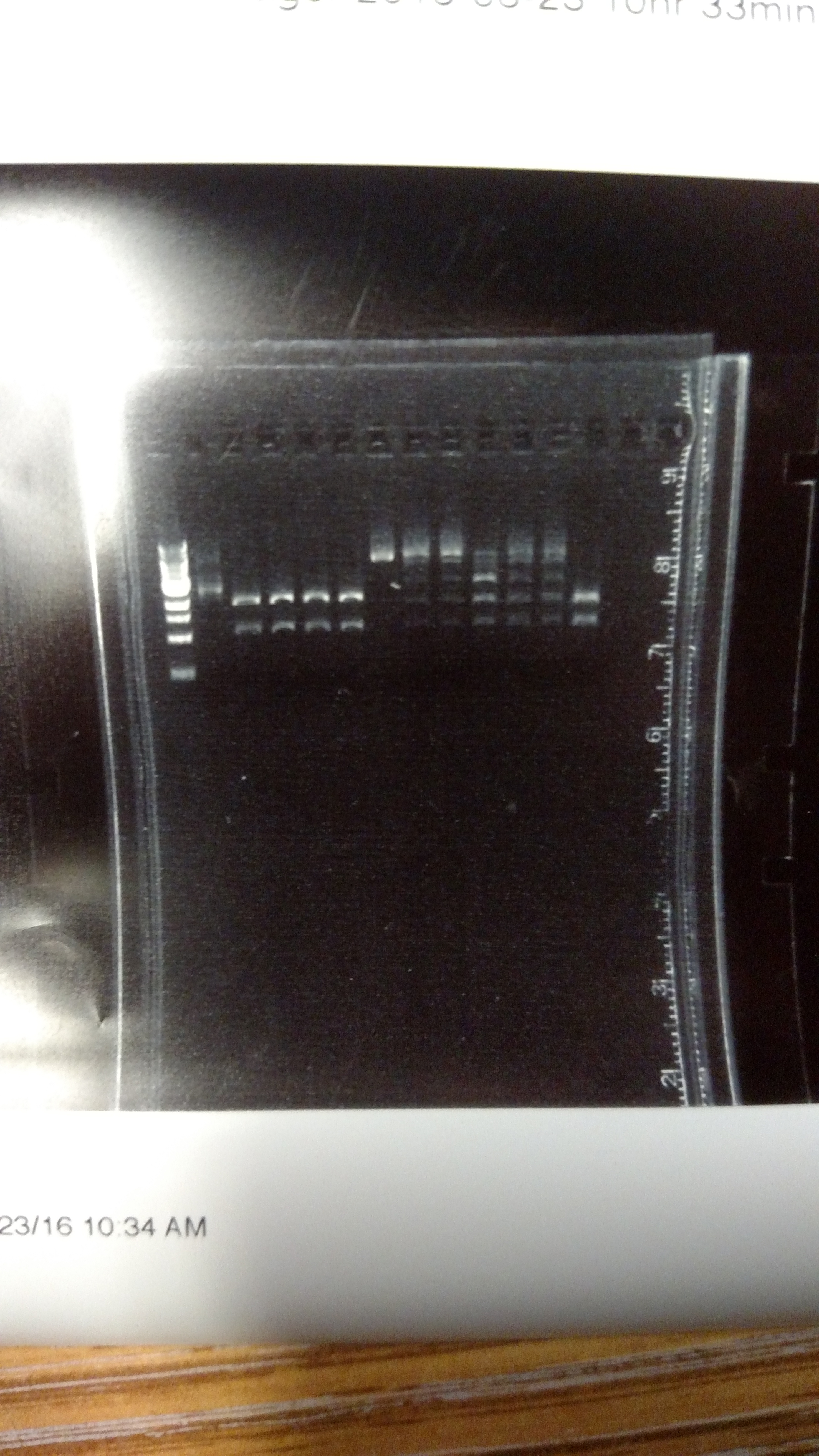
From left to right: (Note: Not sure how to get the text to move over a bit more...-DM)
Based on the above reactions, a protocol was developed using NEB buffer 3.1, supplemented with ATP and DTT to allow for T7 DNA ligase activity. The results can be seen in the PDF below. There are three sets of reactions: The first lane for each set is DNA only, then DNA in a GGA reaction without ligase, and finally DNA in a GGA reaction with ligase. In each set the presence of the ligase results in the formation of higher band products. The procedure was to incubate for 30 minutes with BsmBI at 42°C followed by incubating with T7 DNA ligase at 25°C for 30 additional minutes.
This initial protocol was simply a proof of principle. From this protocol, we are currently using the following protocol. Total volume will be 20 μL; You will need 17.7 ng of pYTK001 and 20 fmol of your DNA insert(s).
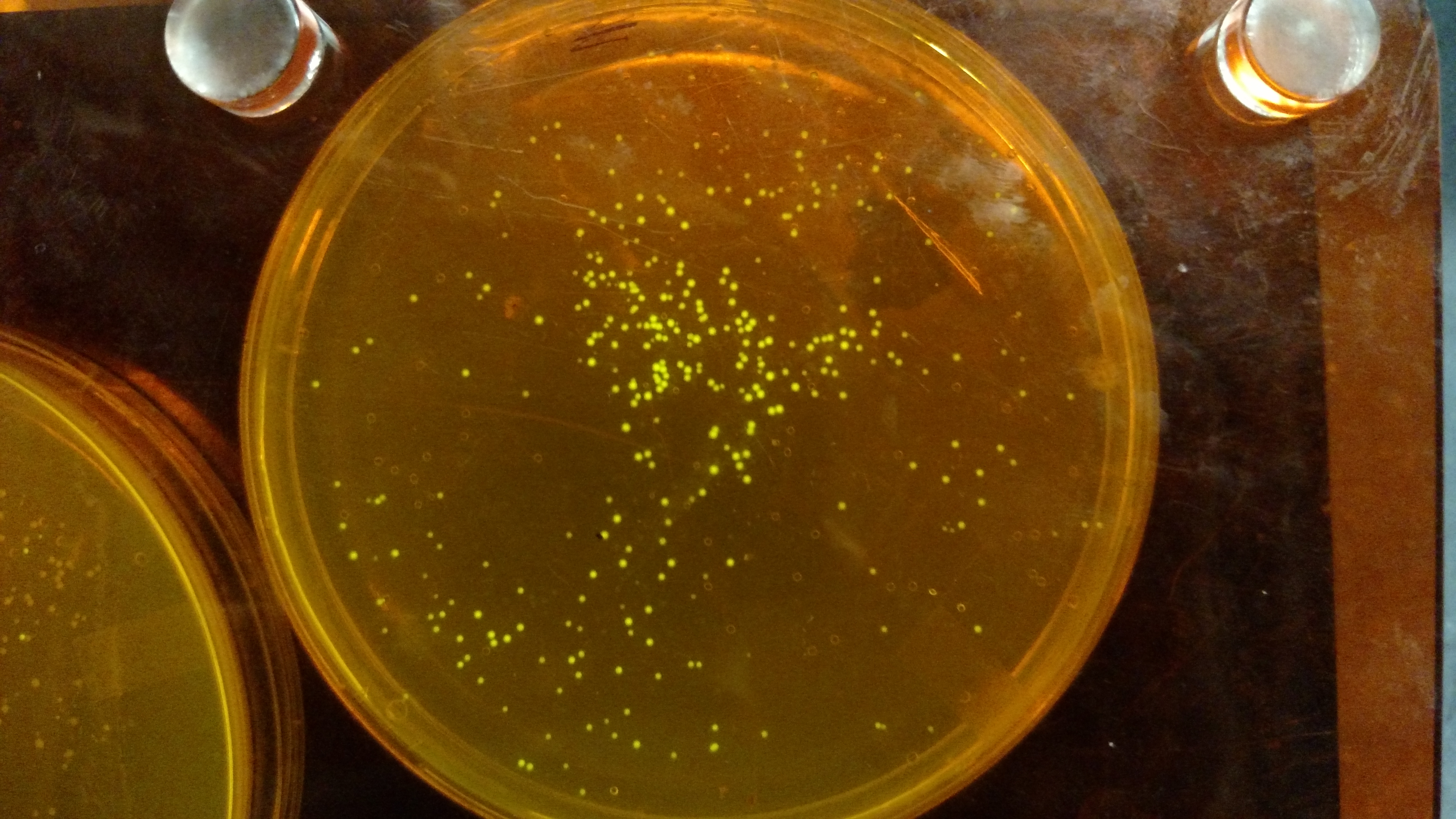
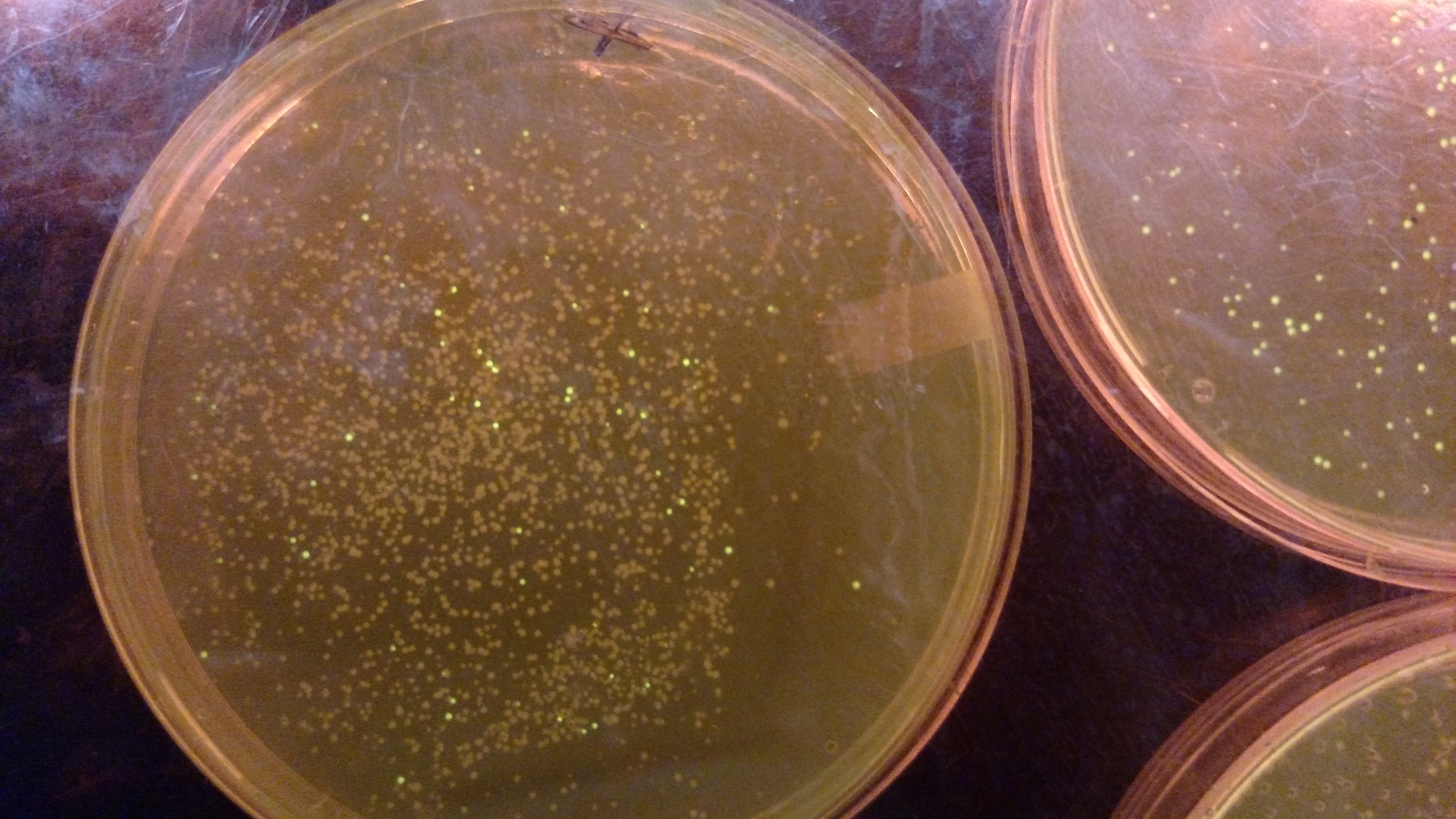
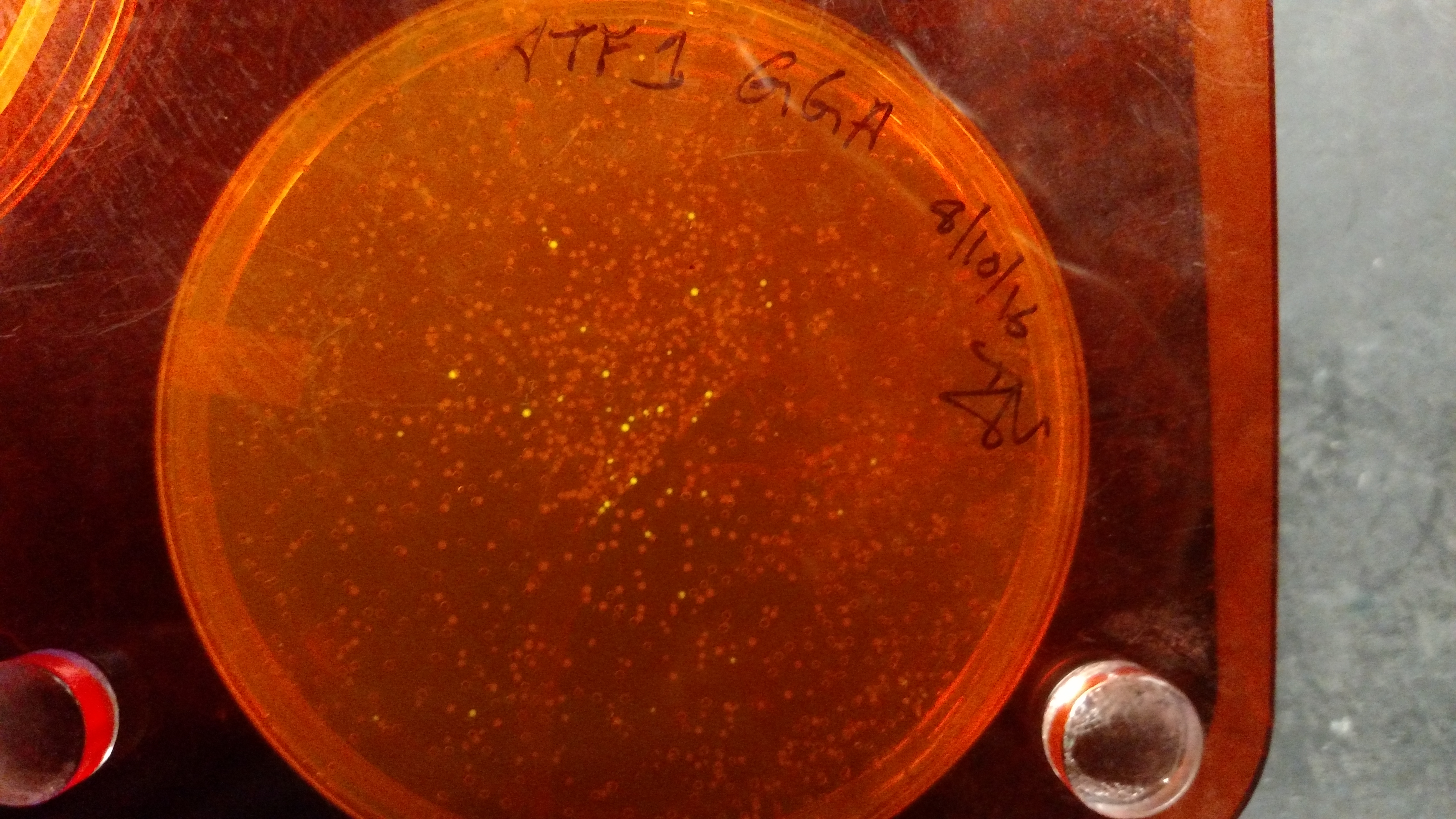
Results and TroubleshootingBelow are three plates from summer 2016. ATF1 (bba_J45014) was added to pYTK001, an entry vector for golden gate assembly. This required removing an internal BsmBI cut site, and then adding the resulting ATF1 gene to pYTK001 using BsmBI. The first plate is a negative control. The golden gate assembly was performed with no gene, just pYTK001. The second plate is a positive control using a gBlock from Peng. The last plate is the actual experimental golden gate assembly where ATF1 inserted into pYTK001.
gBlocks vs PCR products as sequences being assembled.
References
Contributors
| ||||||||||||||||||||||||||||||||||||||||||||||
View topic | History: r18 < r17 < r16 < r15 | More topic actions...
Ideas, requests, problems regarding TWiki? Send feedback